Inhaltsverzeichnis
Troubleshooting in the ignition system
Some basic knowledge about the ignition system
Foreword
 When troubleshooting the ignition system of 912s and 914s, there is unfortunately not always clarity even after intensive study of the manuals.
Even if you have only swapped a plug connector and there is no longer a yellow band near the plug connector, you will have a hard time searching through the manuals. Furthermore, it is tedious to work with the manuals or the printed pages on the engine. Here is an overview of the relevant areas, which are limited to a few printed pages.
Before starting various measurement and control work, please also watch a video from rotaxowner.com:
https://www.youtube.com/watch?v=Wi4v27UG-2Q&t=295s
Here some tests are described in advance.
The arrangement of the pickups
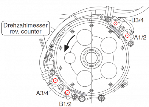
After removing the black ignition cover, you can see the individual ignition sensors and the sensor for the speed signal.
Here you can measure the resistance of the individual sensors once you have disconnected the connectors from the ignition modules.
You check this at the solder joints and the resistance should be 220.0 to 250.0 Ω.
The charging coils on the alternator for the individual ignition modules have already been covered here.
The pickup distance
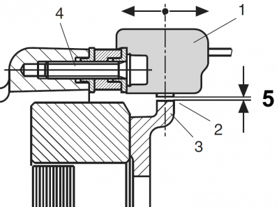
The distance between the pickup and the guide piece of the solenoid hub is decisive for when the ignition timing is switched from the start ignition timing to the operating ignition timing.
See also the article on the function of the softstart modules.
The gap should always be checked if you have worked in the area of the solenoid hub.
It should be in the range between 0.35 and 0.4 mm.
Assignment of the pickups to the spark plugs

This assignment can only be checked reliably with a strobe lamp.
The check also serves to determine whether the magnetic hub is flashed at the beginning of the guide piece or at the end.
If it is flashed at the end when idling, the pickup distance is too large and it has not been switched to the operating ignition timing.
The connection of the ignition coils
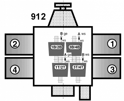
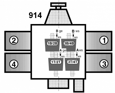
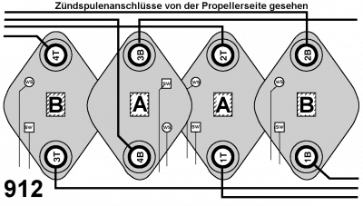
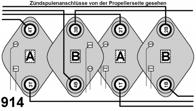
The following images are only intended to provide an overview of which ignition coils are responsible for which two cylinders.
The connection of the individual ignition cables
The pictures show the correct perspective 1), which ignition coil is connected to which ignition cable so that it can be traced to the spark plug.
The assignment is shown from the transmission side.
At first glance, the assignment appears to be the same. This also applies to the ignition cables.
The difference, however, is the assignment of the ignition coils to the ignition circuits A and B.
The assignment is made with different wiring of the ignition modules to the coils.
Resistance of the ignition coils
The resistance of the ignition coils can be measured, but this is difficult to do on the plane as the ignition cables need to be removed.
In addition, these are the parts that fail the least.
Primary ignition coil connection contacts, 0.1 to 0.4 Ω
Ignition coil secondary both ignition cable connections 6.1 to 6.7 kΩ
... and as always:
Attention danger to life !
Working with a running propeller is life-threatening !
Anyone working on a running aircraft engine should always be aware of this and work with extreme concentration.
If in doubt, do not carry out the procedure described!

