Inhaltsverzeichnis
The right power setting for the Rotax
… a tiresome topic that always gets people worked up.
The most common questions are:
- When does the engine have the highest power
- When do I have the least wear
- How do I reduce costs through sensible operation
- At what speed should you start
- How do I recognize the power setting
- which propeller is best and how do I adjust it
Let's start at the beginning with performance and wear.
We'll use the Rotax 912 ULS as an example.
Performance
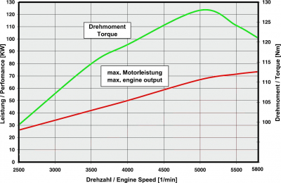
I think the question of performance should be clarified by the diagram and the table.
An important note when using a variable speed governor:
a low power setting at high speed usually leads to a leaner mixture and consequently to an increase in the combustion temperature. The exhaust gas temperature (EGT) should be monitored here.
It is recommended to adjust the RPM according to the power output according to Table 2 (example for a 912 S with 100 HP) (from the Operators Manual)!
Some aircraft manuals or some clubs/ownership associations mistakenly follow the motto “never operate the engine below a certain RPM”.
Unfortunately, this is wrong and here one should orient oneself to the engine speed that is reached when using a fixed-pitch propeller with the corresponding power setting.
The following power tables for operation with a variable speed governor can be found in the operating manuals of the various engines.
Power data for variable-pitch propellers
Operation above 5500 rpm is limited to 5 minutes.
It is recommended to stick to the following values approximately.
Performance table for the 912 A/F/UL (80 HP)
| Power setting | Speed | Power (KW) | Torque (Nm) | Manifold pressure (in.HG) |
|---|---|---|---|---|
| Take off | 5800 | 59.6 | 98.1 | full throttle |
| Continuous | 5500 | 58.0 | 100.7 | full throttle |
| 75 % | 5000 | 43,5 | 83,1 | 27,2 |
| 65 % | 4800 | 37,7 | 75,0 | 26,5 |
| 55 % | 4300 | 31,9 | 70,8 | 26,3 |
Performance table for the 912 S/ULS (100 hp)
| Power setting | Speed | Power (kW) | Torque (Nm) | Inlet manifold pressure (in.HG) |
|---|---|---|---|---|
| Take-off | 5800 | 73.5 | 121.0 | 27.5 |
| Continuous power | 5500 | 69.0 | 119.8 | 27 |
| 75 % | 5000 | 51.0 | 97.4 | 26 |
| 65 % | 4800 | 44.6 | 88.7 | 26 |
| 55 % | 4300 | 38.0 | 84.3 | 24 |
Performance table for the 914 F/UL (115 hp)
| Power setting | Speed | Power (KW) | Torque (Nm) | Intake manifold pressure (in.HG) | Throttle position (%) |
|---|---|---|---|---|---|
| Takeoff power | 5800 | 84.5 | 139 | 39 | 115.0 |
| Continuous power | 5500 | 73.5 | 128 | 35 | 100.0 |
| 75 % | 5000 | 55.1 | 105 | 31 | ca. 67 |
| 65 % | 4800 | 47.8 | 95 | 29 | ca. 64 |
| 55 % | 4300 | 40.4 | 90 | 28 | ca. 59 |
Wear
The question arises as to what speed range the engine should be operated in.
The answer for wide open throttle (WOT) is quite simple (or not) : always let it yodel properly….
… so that means at start 5800 rpm and continuous power 5500 rpm.
The reason for this is simple: the lower the speed, the higher the lateral forces on the piston and the higher the bearing pressures on the connecting rod and crankshaft bearings.
The piston side forces, of all things, must now be “dissipated” via the cylinder wall.
And they will do that in the crankcase..
You can perhaps imagine that these forces lead to a continuous internal movement of the crankcase.
Since we have two crankcase halves, it leads to possible frictional movements within the parting lines.
This frictional movement depends on the crankcase bolting and the resulting surface pressure at the joints.
That is why the crankcases have undergone some modifications to increase precisely this surface pressure and thus ensure that the housing halves no longer rub against each other.
These frictional movements lead to abrasion at the parting surfaces, mainly in the area of the crankshaft main bearings.
Due to the wear in the area of the main bearing points, the bearing bores in the housing become narrower and the crankshaft jams because the play is also reduced to zero or less.
There is also a control instruction in the Line Maintenance Manual.

... see also here: breakaway torque of the crankshaft.
When we talk about wear, we also have to answer the question of where we have the most wear.
We'll leave out all the little things and concentrate on two areas: piston and cylinder wear and wear at the bearing points.
If we assume that the properties of the engine oil meet the specifications, we need not worry about the oil film breaking down at the piston. The mean piston speed at 5800 rpm is only 11.79 m/s.
Let's move on to the bearing points: we have a plain bearing at the big-end of the con-rod and at the main bearings. Plain bearings operate without contact at a predetermined oil pressure. The oil is carried by the rotation of the shaft and forms an oil wedge on which the shaft “floats”, causing it to no longer touch the bearing.
This means that the bearings can support the shaft better at higher speeds due to the more stable oil wedge.
The same applies to the camshaft: a higher circumferential speed generates a more stable oil wedge between the shaft and hydraulic tappet (in the Rotax).
Cost/Benefit
Particularly in the charter business and with a controllable pitch propeller, it is often thought that you can save a lot of fuel and money at full throttle and at speeds below 4800 rpm, while still achieving a high cruising speed.
This is even partially true, but it is a financial miscalculation…
… because a crankcase that needs to be replaced, which is worn in the area of the main bearings, costs considerably more than you save in fuel in the time flown so far.
It was not for nothing that we had the following in the SL-912-016 / SL-914-014 from 2009:
Solution recommendations
| Step | Procedure |
|---|---|
| 1 | Engine speed above 5500 1 /min is limited to a maximum of 5 min (as specified in the 912/914 series operating manual). |
| 2 | Starting speed at WOT (fully open throttle) should not be below 5200 Ilmin to avoid overloading the engine. |
| 3 | Continuous use of engine speeds below 5200 rpm with WOT should be avoided. |
In the last revision of the service letter, only fuel quality is discussed at this point, which in my opinion only leads to confusion and is not practical in flight.
The fixed-pitch propeller
This includes the ground-adjustable propeller, because you can't really fiddle with it in flight.
We'll leave out the differences between the various numbers of blades, propeller sizes and aircraft types for now.
Basically, we have the problem that it is not possible to adjust the blade angle for different speeds – that's why our airfoil is called a fixed-pitch propeller.
So what setting do you choose?
Here is my humble opinion on how to set the blade angle:
In level flight, at full throttle, top speed and at my preferred cruising altitude, the engine should reach an rpm of approx. 5700.
The reason for this is that if I fly slower, I reduce the throttle to cut down the power, which saves the engine and my wallet. I also stay close to the 5500 rpm specified for continuous power without flying with WOT.
The problem with this is mainly with the 914 and the fuel-injected engine: as you fly higher, the air gets thinner and the engine revs higher, possibly exceeding 5800 rpm.
With the 912 UL and ULS, the effect is less pronounced because the engine is heavily supercharged at altitude and thus loses power.
So I would consider this to be the optimal setting for the flight. What happens during takeoff is a different matter and I would then have to live with it. The question is, do I want to fly economically and gently on the engine or do great takeoffs?
Of course, with such a setting, the higher the aircraft's maximum speed, the worse the behavior during takeoff.
What can also happen is that if we apply full throttle when stationary and want to take off, i.e. when the propeller plane is not traversed by the airflow, the airflow on the blade will break away.
This means that, of course, not all of the engine power can be converted into propulsion and, in addition, it also gets noisy. So you can't take off at full power and you choose the take-off power so that the airflow just doesn't break away.
As the speed increases, the power can be increased and the plane climbs more steeply.
==== The variable pitch propeller =====….
or the gear shift in an airplane….
There are three different types of variable pitch propellers:
- the hydraulic constant speed propeller
- the electric constant speed propeller
- and the electric variable pitch propeller
You can find an article about the hydraulic constant speed propeller here: article in Aerokurier and you should read Manifold Pressure Sucks! as a matter of principle as a pilot. It is important to note that they are always talking about the propeller speed!
Not addressed here is an electrically controlled, hydraulic constant speed governor that is available for the 912 iS and 915 iS.
The optimum power setting is always achieved by the Stock EMU in conjunction with the governor supplied by MT-Propeller.
The electrically adjustable constant speed propeller and the adjustment are the same as for a hydraulic propeller, with the disadvantage that the electrically adjustable one reacts much more slowly. This can result in unintentional overspeeding of the engine.
The electrically adjustable propeller during the flight requires special attention of the pilot and presupposes thereby in my opinion a minimum of experience and technical understanding.
Of all the propellers adjustable in flight, however, there is a certain risk to the service life of the engine.
It is possible to operate the engine at full throttle and to reduce the speed by adjusting the propeller.
This can be done to such an extent that the Rotax, as I have often heard, is choked down to 4600 rpm. This can then lead to uncontrolled combustion (knocking / ringing) of the mixture and thus to engine damage.
….or to crankcase damage, as described above…
I have seen a damaged engine block (caused by “rubbing”) in a charter plane in just such a case, with less than 400 operating hours.
Remember: keep the Rotax turning, and it will stay healthy!
Power setting in %
Finding this out is very easy:
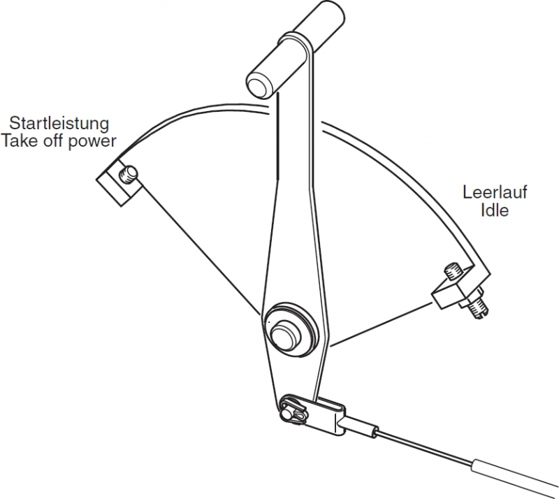
idle is 0% and full throttle is 100%.
… you measure the lever travel of the throttle, divide the value by 100 and make a mark at half the distance with a marker and you already know when you are flying at 50% power. At 75% power, it's just 3/4 of the measured distance…
Here in the picture, therefore, about 50% power. Whether the engine power output is actually 50%, would have to be determined in elaborate experiments. However, I consider the method with the simple classification of the throttle range to be a useful basis for communication.

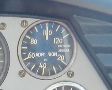
I can already hear the objection that there is an instrument for that, namely a Manifold Pressure Gauge.\\…
but show me one with a % display…
… someone has done it - many thanks to Edi from the Oberpfalz!
Unfortunately, the instrument cannot be used for a Rotax and it seems to me that this is a boost pressure gauge with a scale tailored to the engine. As you can see, it shows 100% when the engine is stationary, which corresponds to the ambient pressure.
I couldn't get this out of my mind, so I came across an article that deals
with the determination of power.
I took the liberty of translating the article into German, which can be downloaded here as PDF
On November 11, 2024, Rotax published the SB-912-079 in response to complaints about frequent engine failures during take-off.
The performance adjustment is explicitly mentioned here in section 3.5) Engine load from page 15.

